Abstract: A field-effect transistor is used to design a bile-quality audio power amplifier. The front stage adopts single tube and class A, and the latter stage adopts class A and B type push-pull amplification technology. Experiments show that the consistency of the tube used by the differential amplifier is closely related to the degree of distortion of the whole machine. From the listening effect, the final current 200mA is an ideal value.
This article refers to the address: http://
The coupling capacitance between the front and the back has a great influence on the listening sound, and the quality is required to be higher.
For audio power amplifiers, it is best to listen to Class A amplifiers. According to the results of the frequency analysis, the front stage sound composed of the integrated operational amplifier is thin and lacks vitality. Therefore, it is not necessary to use a single-tube class A amplifier in the previous stage, and a class-A power amplifier in the latter stage. This requires both listening and sound efficiency. At present, tube audio power amplifier still occupies the high-end market of audio equipment. Can I use a field effect transistor (FET) to achieve a long, mellow sound like a tube amplifier? I made an FET-based amplifier based on the transistor power amplifier, and achieved a bold music effect. .
1 The advantages of amplifiers with FETs as basic components are obvious
For the three components currently used in amplifiers, the input impedance of the transistor is too low (about 1 k), the input impedance of the tube is high, but the output impedance is also high. To this end, an output transformer is added. Make the volume larger and consume more power. So neither is an ideal output tube. Overall, FETs have high input impedance and can output large currents, making them ideal for single-ended Class A amplifiers. The mid-range is full, delicate and smooth, and full of flexibility. Amplifiers made with FETs produce shocking low-frequency bombing sounds.
1.1 Low distortion
The FET is less distorted than the transistor and slightly larger than the bile duct. Most of them are even harmonic distortion, which makes the sense of hearing better. The distribution of high and low frequency energy is appropriate, the sound has density, the low frequency is deeper, the sound field is stable, the transparency is moderate, the sense of layering, resolution and positioning. Both have good performance, good sound field space rendering ability, and good performance for music details.
The transconductance of the FET is linear. The linear area is broad and very similar to the transmission characteristics of the tube. Better linearity means lower distortion.
1.2 Low noise
The noise of the FET is very low and the noise figure can be less than 1 dB. Taking 2SK30 as an example, the typical value of the noise figure is 0.5 dB under the test conditions of VDS=15 V, VGS=0V, RG=100 kΩ and f=120 Hz. The noise figure is defined as the signal-to-noise ratio of the input signal of the system divided by the signal-to-noise ratio of the output signal of the system, expressed in decibels:
NF=20*log([Si/Ni]/[So/No])
Si = power of the input signal
So = power of the output signal
Ni = input noise power
No=output noise power
1.3 High stability
We know that Class A power amplifiers have low thermal efficiency and generate more than 70% of the total power consumed. The thermal stability of the circuit is more affected by temperature. If the thermal stability of the circuit is poor, the listening effect will be abnormal. This makes most audiophiles look down. The main link affecting the stability of the circuit is the current amplification part of the amplifier circuit, also called the output stage. The bipolar transistor collector current has a positive temperature coefficient, ie its collector current increases with increasing temperature. The FET is just the opposite and has a negative temperature coefficient, ie
His drain current decreases as its junction temperature increases. The temperature compensation circuit is used for the bipolar transistor of the push stage and the output stage to ensure that the static operating point of the output transistor does not change with the change of the ambient temperature. With the field effect transistor, the temperature compensation circuit can be omitted, thereby greatly improving the stability of the amplifier.
2 Circuit structure of an amplifier with a field effect transistor as a basic component
2.1 The composition of the pre-level
The FET single-tube class A preamplifier is shown in Figure 1. The Tn source potential is measured to be 0.5 V, the drain potential is 5.0 V, and the drain current IDSS is equal to 1.25 mA. According to the relevant contents of the 2SK30AMT factory manual, the linearity of this working point is the best.
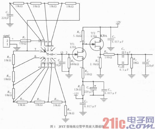
The amplification factor of this stage amplifier is calculated according to the formula Au=-gmRf3, where gm is the transconductance of the field effect transistor.
The minimum transconductance gm = 2 ms for 2SK30AMT at VDs = 10 V and VGS = 0 V. Then the amplifier of this stage has a magnification of 6.72.
The volume adjustment is performed by adding 11 fixed resistors to the advanced switch, each resistor 10k. The advantage of doing this is that it is both economical and of good quality. The volume adjustment is really 10 levels, and the listening effect is very good.
The second stage amplifying circuit is used as a source output device, which is designed to match the circuit and improve the load capacity of the front stage, and the amplification factor is approximately 1. The quiescent operating point is still very important. The Tf2 source potential is measured at 5.5 V, which is well near the median of the supply voltage. At this stage, the drain current can be calculated as 2.75 mA, which also satisfies the static requirements of Class A amplifiers.
Straight-through capacitors C17 and C18 have a great influence on the sound quality. Imported brand-name WIMA capacitors are used.
2.2 The post-amplifier circuit still uses push-pull type, class A and B amplifiers.
The components used in the symmetrical amplifier circuit are tested for their static characteristics. The power amplifier circuit is shown in Figure 2.
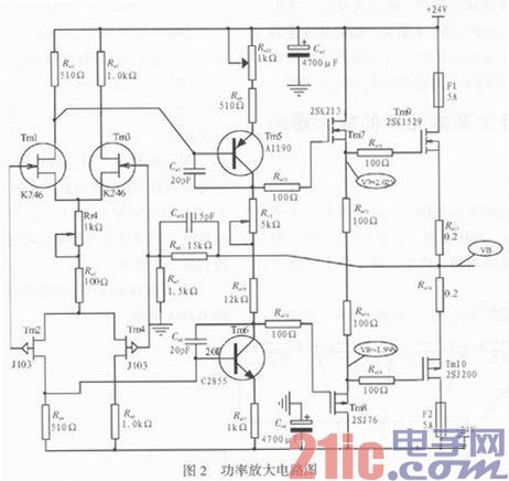
Taking Tm1 and Tm3 as examples, the detection parameter is mainly IDDS, that is, the drain current when VGS=0. When VGS=0, the IDDS is measured, and the values ​​are similar. Similarly, Tm2 and Tm4 should be similar to or similar to the static values ​​of Tm1 or Tm3. Only if the static values ​​of these four FETs are roughly the same, it is possible to make a good quality amplifier. The mass production of amplifiers is very high, and it is the matching of components used in these circuits that is difficult to manufacture, which results in high manufacturing costs and restricts the popularization and application of the technology.
The matching of these four FETs is crucial, and only their static characteristics are consistent, so as to ensure the accuracy and safety of the operation of the high-power amplifying components. The complementarity requirements of the push and output stages correspond to the differential amplifiers, which are not described here. Please refer to the above for the reader.
2.3 Commissioning of the whole machine
The setting of the static value of the final stage (Tm9 and Tm10) current has a greater influence on the listening effect, and the sound is warmer and softer, but the efficiency is lowered. Too big, bad trouble can damage the power device. Adjusting Rm22 can change the gate potential of Tm7 and Tm8, which in turn affects the gate potential and final current of Tm9 and Tm10. When initially commissioning, it is best to remove the Tm9 and Tm10 high power FETs from the circuit. When adjusting Rm22, the eyes are closely fixed to the midpoint potential (VB). If VB is greater than 0 V, Rm22 is increased, otherwise, Rm22 is decreased. After adjusting the midpoint potential, two high-power FETs, Tm9 and Tm10, are installed to ensure the safety of high-power components.
The voltage drop across Rm3 and Rm4 is preferably 2 V. Too high will cause the quiescent current of the rear stage (Tm9 and Tm10) to be too large; too low will make the sound distortion the most. Adjusting Rr4 can regulate this voltage.
In order to improve the spirituality of playback, the amount of feedback should not be too large, determined by Rm7 and Rm8. Here, the feedback coefficient is chosen to be 0.1, which is ideal from the listening effect.
3 key technologies of the amplifier
3.1 Key technologies of the front and rear stages
In the concept of simplicity and supremacy, minimize redundant links and reduce negative feedback. In a circuit consisting of an integrated operational amplifier, the sound lacks vitality and the sound field is in a plane. Therefore, this circuit does not use any integrated circuit.
For a symmetrical amplifier, the choice of the tube determines the quality of the amplifier circuit. To some extent, the amplifier is the opposite tube.
For the preamplifier circuit, the VGS design of the two junction FETs (Tf1 and Tf2) is ideal for -0.5 V, which is based on their output characteristics.
V7, V8 (see Figure 2) the level of the potential, affecting the sound quality of the sound, the potential difference is larger, the sound will be thicker, the charm is more. On the contrary, the sound is worse. The potential of V7 and V8 is adjusted by adjusting the potentiometer Rr3. When the resistance of Rr3 is decreased, the potential difference between V7 and V8 is also reduced. In Figure 2, the voltage values ​​of V7 and V8 are ideal. At this time, the final current is about 200 mA. If it is too small, the sound is too cold, pale and powerless; too big, costly, and does not help the improvement of sound quality.
3.2 Power quality is critical to the amplifier
The ±24 V regulator circuit is shown in Figure 3. The power supply has a soft start function and has a protection function that the positive and negative power supplies are short-circuited or short-circuited at the same time. When any one of the positive and negative power supplies is shorted to ground, the negative and positive supply voltages will be zero, thereby protecting the output tube of the power amplifier circuit. There is no large DC current in the speaker, which effectively protects the speaker.
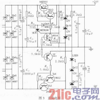
The soft start circuit of the power supply can eliminate the large current that impacts the speaker when the power is turned on, and avoids an instant "click" when the power is turned on. The soft start circuit consists of Rs9, Cs9, R10, Ds9, Rs11, Rs 12 and thyristor SCR. The power-on delay time is determined by the Rs9, Cs9 time constant. In this example, the constant is 0.47 s. There is no “beep†in the speaker at boot time.
3.3 Other
High current line wiring width 100 mil, plus tin. The ground wire is also 100 mil, plus tin.
In addition to the capacitors for power supply filtering, all high-quality WIMA capacitors from Germany are used.
4 amplifier noise reduction measures
It is strictly forbidden to cross the front and rear stages when placing component wiring.
Low mass of the potentiometer will cause more obvious noise.
The front and rear power supplies must be separated, otherwise the large dynamic signals from the rear stage will be sent to the front stage through the power supply, causing obvious interference.
5 Conclusion
The amplifier can be done well to achieve a small sound reproduction, high-frequency extension transparency, heavy bass, and a mid-range stretch. Through experimental comparison, the amplifier made by the FET has low noise figure, rounded sound, small volume and unique charm.
Electric Car,Electric Shuttles,Best Small Electric Car,Four-Wheel Electric Vehicle
Jinan Huajiang environmental protection and energy saving Technology Co., Ltd , https://www.hjnewenergy.com